02 Grand cherokee with broken heater fan -- have codes, now what?

Lol, Sorry. It's impossible to get a higher reading from a component connector than the actual battery voltage. A submarine with a Nuclear powerplant however may exibit that symptom depending where you stick that probe. :redface:. You must have probed for the Battery voltage where there's a resistance to give you a lower reading than the component connector.The fact that you have 12volts or battery voltage coming out of the wire is a good sign. If this connector is the one FROM the resistor to the blower, then this will also have a variable resistance on the circuit depending on the HVAC setting. Test the output on these wires on low, med and high. if they all give you a different voltage other than zero, then that circuit is good. Replace the overheated connectors and wires. If the component (Blower, Resistor block) connectors are also showing signs of heat damage, i would suggest that you replace thos as well. Otherwise it might end up doing the same thing down the road.. If i remember correctly, i once read on a memo that there was a change in design of the blower resistor block for a higher heat dissipation.
 
I thought it was odd, but I measured the battery voltage straight across the battery. I am going to pick up the replacement connector today.

You don't think I need to replace the resistor or the blower motor unless there is visible heat damage?
 

I would only suggest to replace the connectors that has been damaged including the component that you had to pry the connector off from. The rest is up to you to make the call. I would suspect that the resistor block is the old design. The newer one's are designed to dissipate the heat a lot quicker. With this in mind, you probbably would like to replace that as well. Since you didn't have to bump the motor to get it working, i will leave that alone.
 
Well, I replaced the connector, and the blower is blowing reliably.

The housing for the resistor block was melted much more badly than I had thought.

I suppose I should replace the resistor block.

I read on wjjeeps.com that I should check the current draw on the blower and see if it is between 13-17amps to see if the blower is bad. How do I do that? I really don't know how to use my multimeter beyond measuring voltage.

I guess I just don't understand why it failed in the first place. I want to try to make sure it doesn't happen again.

Thanks a bunch for all the help, I really appreciate it.:shades:
 
How To: http://www.allaboutcircuits.com/vol_1/index.html

LEARNING OBJECTIVES
  • How to measure current with a multimeter
  • How to check a multimeter's internal fuse
  • Selection of proper meter range

SCHEMATIC DIAGRAM
05056-2.png


ILLUSTRATION
05057-2.png


INSTRUCTIONS
Current is the measure of the rate of electron "flow" in a circuit. It is measured in the unit of the Ampere, simply called "Amp," (A).
The most common way to measure current in a circuit is to break the circuit open and insert an "ammeter" in series (in-line) with the circuit so that all electrons flowing through the circuit also have to go through the meter. Because measuring current in this manner requires the meter be made part of the circuit, it is a more difficult type of measurement to make than either voltage or resistance.
Some digital meters, like the unit shown in the illustration, have a separate jack to insert the red test lead plug when measuring current. Other meters, like most inexpensive analog meters, use the same jacks for measuring voltage, resistance, and current. Consult your owner's manual on the particular model of meter you own for details on measuring current.
When an ammeter is placed in series with a circuit, it ideally drops no voltage as current goes through it. In other words, it acts very much like a piece of wire, with very little resistance from one test probe to the other. Consequently, an ammeter will act as a short circuit if placed in parallel (across the terminals of) a substantial source of voltage. If this is done, a surge in current will result, potentially damaging the meter:
05058-2.png

Ammeters are generally protected from excessive current by means of a small fuse located inside the meter housing. If the ammeter is accidently connected across a substantial voltage source, the resultant surge in current will "blow" the fuse and render the meter incapable of measuring current until the fuse is replaced. Be very careful to avoid this scenario!
You may test the condition of a multimeter's fuse by switching it to the resistance mode and measuring continuity through the test leads (and through the fuse). On a meter where the same test lead jacks are used for both resistance and current measurement, simply leave the test lead plugs where they are and touch the two probes together. On a meter where different jacks are used, this is how you insert the test lead plugs to check the fuse:
05059-2.png

Build the one-battery, one-lamp circuit using jumper wires to connect the battery to the lamp, and verify that the lamp lights up before connecting the meter in series with it. Then, break the circuit open at any point and connect the meter's test probes to the two points of the break to measure current. As usual, if your meter is manually-ranged, begin by selecting the highest range for current, then move the selector switch to lower range positions until the strongest indication is obtained on the meter display without over-ranging it. If the meter indication is "backwards," (left motion on analog needle, or negative reading on a digital display), then reverse the test probe connections and try again. When the ammeter indicates a normal reading (not "backwards"), electrons are entering the black test lead and exiting the red. This is how you determine direction of current using a meter.
For a 6-volt battery and a small lamp, the circuit current will be in the range of thousandths of an amp, or milliamps. Digital meters often show a small letter "m" in the right-hand side of the display to indicate this metric prefix.
Try breaking the circuit at some other point and inserting the meter there instead. What do you notice about the amount of current measured? Why do you think this is?
Re-construct the circuit on a breadboard like this:
05052-2.png


Students often get confused when connecting an ammeter to a breadboard circuit. How can the meter be connected so as to intercept all the circuit's current and not create a short circuit? One easy method that guarantees success is this:
  • Identify what wire or component terminal you wish to measure current through.
  • Pull that wire or terminal out of the breadboard hole. Leave it hanging in mid-air.
  • Insert a spare piece of wire into the hole you just pulled the other wire or terminal out of. Leave the other end of this wire hanging in mid-air.
  • Connect the ammeter between the two unconnected wire ends (the two that were hanging in mid-air). You are now assured of measuring current through the wire or terminal initially identified.
05060-2.png

Again, measure current through different wires in this circuit, following the same connection procedure outlined above. What do you notice about these current measurements? The results in the breadboard circuit should be the same as the results in the free-form (no breadboard) circuit.
Building the same circuit on a terminal strip should also yield similar results:
05061-2.png

The current figure of 24.70 milliamps (24.70 mA) shown in the illustrations is an arbitrary quantity, reasonable for a small incandescent lamp. If the current for your circuit is a different value, that is okay, so long as the lamp is functioning when the meter is connected. If the lamp refuses to light when the meter is connected to the circuit, and the meter registers a much greater reading, you probably have a short-circuit condition through the meter. If your lamp refuses to light when the meter is connected in the circuit, and the meter registers zero current, you've probably blown the fuse inside the meter. Check the condition of your meter's fuse as described previously in this section and replace the fuse if necessary.
 

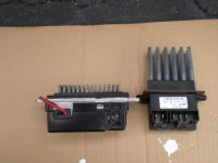
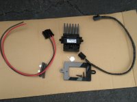
OK, so the old connector upgrade is obsolete. The new resistor module now has a massive heat sink. See photo with side by side comparison. (old on left new on right).

To do the upgrade you also need an adapter kit. The par #s are 68052436AA and 5179985AA 420D (about $100 total)

I did the upgrade, but while I was wiring in the connector, I saw a spark fly. I didn't have the key in the ignition. But now, the blower won't work. Did I ruin the main control? The numbers work on it, but the fan won't blow. I did the ACZ diagnostic and all of the lights on the display come on. I don't see where I would have blown a fuse. And of course I now realize that I should have disconnected the battery, but I didn't think it would have power going to it with the ignition off.:redface:

When I turn the fan on, there is no voltage reading going into the resistor module.
 

Attachments

  • DSCN0086.JPG
    DSCN0086.JPG
    543.1 KB · Views: 1,208
  • DSCN0087.JPG
    DSCN0087.JPG
    474.9 KB · Views: 1,294
Both fuses good on the Junction block and the PDC?. Now you can see the "Revision" on the new resistor. As for the Battery disconnect, i was almost certain that you knew what your doing. lol. Just kidding. One of the fuses is probbably blown, check those first.
 
Last edited:
OK, I checked the fuse in the PDC, and it was bad. I replaced it and the blower is blowing. But now it will only blow on the floor.

It won't blow out of the vents. Error codes are 52, 53, 55.
 
Nevermind, brainfart.. Perform a battery disconnect and then perform the calibration procedure.
ENTERING THE AZC SELF-DIAGNOSTIC MODE


To enter the AZC self-diagnostic mode, perform the following:
  1. Depress the a/c and recirc buttons at the same time and hold. Rotate the left temperature control knob clockwise (CW) one detent.
  2. If you continue to keep the a/c and recirc buttons depressed, the AZC control module will perform a Segment Test of the Vacuum Fluorescent (VF) display. In the Segment Test you should see all of the display segments illuminate as long as both buttons are held. If a display segment fails to illuminate, the vacuum fluorescent display is faulty and the a/c heater control must be replaced.
  3. After viewing the Segment Test, release the A/C and Recirc buttons and the display will clear momentarily. If a 0 is displayed, then no faults are set in the system. Should there be any faults, either "current" or "historical", all fault codes will be displayed in ascending numerical sequence (note no effort is made to display fault codes in chronological order). Each fault code is displayed for one second before the next code is displayed. Once all fault codes have been displayed, the system will then repeat the fault code numbers. This will continue until the left side set temperature control is moved at least one detent position in the CW direction or the ignition is turned "OFF".
FAULT CODE TESTS


Fault codes are two-digit numbers that identify a circuit that is malfunctioning. There are two different kinds of fault codes.
  1. Current Fault Codes - Current means the fault is present right now. There are two types of current faults: input faults, and system faults.
  2. Historical Fault Codes - Historical or stored means that the fault occurred previously, but is not present right now. A majority of historical fault codes are caused by intermittent wire harness or wire harness connector problems.
CURRENT FAULT CODES


Input faults
01 = IR thermister circuit open
02 = IR thermister circuit shorted
03 = Fan pot shorted
04 = Fan pot open
05 = Mode pot shorted
06 = Mode pot open
07 = IR sensor delta too large
08 = Reserved
09 = Reserved
10 = One of four motor drivers has drive "A" shorted to ground
11 = Engine air intake temperature Buss message missing
12 = Country code Buss message missing
System Faults
13 = Mode motor not responding
14 = AI (Recirc) motor not responding
15 = Left temperature door not responding
16 = Right temperature door not responding
17 = Mode door travel range too small
18 = Mode door travel range too large
19 = AI (Recirc) door travel too small
20 = AI (Recirc) door travel too large
21 = Left temperature door travel too small
22 = Left temperature door travel too large
23 = Right temperature door travel too small
24 = Right temperature door travel too large
25 = Calibration check sum error
26 = Engine coolant temp bus message missing
27 = Vehicle speed bus message missing
28 = Engine RPM bus message missing
29 = OAT bus message missing
30 = Display intensity bus message missing
31 = VIN number bus message missing
32 = Raw OAT bus message missing


HISTORICAL FAULT CODES


Input faults
33 = IR thermister circuit was open
34 = IR thermister circuit was shorted
35 = Fan pot was shorted
36 = Fan pot was open
37 = Mode pot was shorted
38 = Mode pot was open
39 = IR sensor delta was too large
40 = Reserved
41 = Reserved
42 = One of four motor drivers had drive "A" shorted to ground
43 = Engine air intake temperature Buss message missing
44 = Country code Buss message missing
System Faults
45 = Mode motor was not responding
46 = AI (Recirc) motor was not responding
47 = Left temperature door was not responding
48 = Right temperature door was not responding
49 = Mode door travel range too small
50 = Mode door travel range too large
51 = AI (Recirc) door travel range too small
52 = AI (Recirc) door travel range too large
53 = Left temperature door travel too small
54 = Left temperature door travel too large
55 = Right temperature door travel too small
56 = Right temperature door travel too large
57 = Calibration check sum error
58 = Engine coolant temp bus message missing
59 = Vehicle speed bus message missing
60 = Engine RPM bus message missing
61 = OAT bus message missing
62 = Display intensity bus message missing
63 = VIN number bus message missing
64 = Raw OAT bus message was missing
65 = Reserved
66 = Reserved
67 = Reserved
5. NOTE: A battery disconnect will erase all faults stored in Random Access Memory (RAM) of the AZC control module. It is recommended that all faults be recorded before they are erased.
6. RETRIEVING FAULT CODES

1. To begin the fault code tests, depress the A/C and Recirc buttons at the same time and rotate the left temperature control knob clockwise (CW) one detent, then release the push-button.
2. If there are no fault codes, the “00” display value will remain in the VF window. Should there be any codes, each will be displayed for one second in ascending numerical sequence (note: no effort is made to display faults in the order they occurred). The left side set temperature display will be blanked and the right side set temperature display will indicate current and historical codes (8 historical max) presently active. Once all codes have been displayed, the system will repeat the fault code numbers. This will continue until the left side set temperature control is moved at least one detent position in either direction, by pressing both the A/C and Recirc buttons at the same time, or the ignition is turned off. Record all of the fault codes, then see the Current and Historical Fault Code charts for the descriptions.
CLEARING FAULT CODES

Current faults cannot be electronically cleared. Repair must be made to the system to eliminate the fault causing code. Historical fault codes can be cleared manually, or automatically. To clear a historical fault manually, depress and hold either the A/C or Recirc button for at least three seconds while the display is in the fault code mode of operation. Historical fault codes are cleared automatically when the corresponding current fault code has been cleared, and has remained cleared for a number of ignition cycles. The faults have been cleared when two horizontal bars appear in the Test Selector display.
EXITING SELF-DIAGNOSTIC MODE

The self-diagnostic mode can be exited by pressing both the A/C and Recirc buttons at the same time, or turning off the ignition.
MONITOR CURRENT PARAMETERS

While in the display fault code mode of operation, current system parameters can also be monitored and/or forced. Rotating the left side set temperature control clockwise will increase the pointer number while rotating the control counter clockwise will decrease the pointer number. Rotating the right set temperature control will have no impact on pointer value or the value of the parameter being monitored. Once the desired pointer number has been selected, pressing either the AC or Recirc buttons will display the current value of the selected parameter. The right side set temperature display is only capable of displaying only values ranging from 0 to 99, the left side set temperature display is used for values greater than 99. If the value is less than 99, the left side set temperature display remains blanked. While a parameter is being overridden, the system will continue to function normally except for the parameter which is being manually controlled.
For values < 0, the "G" segment in the left side set temperature Most Significant Digit (MSD)(or left-most number in the pair) will be used to indicate a negative number. For values between -01 to -99 the Least Significant Digit (LSD)(or right-most number of the pair) in the left side set temperature will remain blank. System control of parameter being displayed can be overridden by rotating the right set temperature control in either direction. Rotating the right temperature control in the CW direction, the selected parameter value is overridden and incremented beginning at the value which was being displayed. Rotating the right temperature control in the CCW direction, the selected parameter value is overridden and decremented beginning at the value which was being displayed. The rate at which incrementing and decrement occurs is one unit value per set temperature detent position.


OUTPUT CIRCUIT/ACTUATOR TESTS

In the Output Circuit/Actuator Test mode, the output circuits can be viewed, monitored, overridden, and tested. If a failure occurs in an output circuit, test the circuit by overriding the system. Test the actuator through its full range of operation.
3. To begin the Output Circuit/Actuator Tests you must be in the Select Test mode.
4. With a “00” value displayed in the Test Selector and no stick man, turn the rotary temperature control knob until the test number you are looking for appears in the Test Selector display. See the Circuit Testing charts for a listing of the test numbers, test items, test types, system tested, and displayed values.
5. To see the output value, depress the a/c or recirc button. The values displayed will represent the output from the AZC control module.
6. To enter the actuator test, depress the a/c or recirc button. Then, rotate the right temperature set knob to the desired position.
 
OK, this is messed up.

I replaced the fuse, wired everything up, the blower was spinning, but it didn't sound right. It sounded like it was sucking. But air was coming out of the vents.

Now, there is no way I could have screwed it up. On the resistor block connector splice, I connected the wires per the instructions. It says "Following the 4-way pigtail color coding splice 3 wires to the vehicle wiring." So, I spliced the black to the black; the red to the red; and the striped to the striped. On the blower motor plug, there is no splicing, just plug in.

Air was only coming out of the bottom ducts, and the fan sounded really weird.

So I did th AZC recal. No luck.

So, I put the old resistor block in and did an AZC recal, and everthing works and no error codes. I have no idea why. I couldn't have screwed the new resistor up, because it was still in the package when I had my wiring hiccup.

Anyway, I have a $100 resistor, and the Jeep garage says no returns on electronics. I'll give it a try anyway. I don't dare try to wire it up any other way than black-black, red-red, etc. Everything is working, and I am not chancing any more errors.

I have no idea...

I've done the connector wiring twice now with the old style connector and it worked with no problems. With the new connector, it screwed up my mode selection.
 

If worse comes to worse. Tell the people you bought the resistor block from that the part is defective and you would like a replacement , not a refund. If they ask what's wrong, just say there's no power coming out of the resistor block to the blower circuit and the old part you have works just fine with the exemption that the connectors are overheated. 9 out of 10 times, the parts dept. will honor a defect on an electrical part if you show them that you know what your talking about.
 
the parts dept. will honor a defect on an electrical part if you show them that you know what your talking about.
I think I've demonstrated that I know that I'm talking about here :shades:, just kidding.

But I seriously don't think I screwed it up. I'll try to explain that I wired the old one up correctly twice without problems, and it's not color coded. So I must know what I'm doing to some extent.
 
I forgot to mention last night. Bring your insurance card with the VIN# of your GC to a dealer and have them check it for Recalls. Specifically the F-25. This is a free replacement of the radiator fan module on some of the GC's depending on the Vin breakpoints.
 

I forgot to mention last night. Bring your insurance card with the VIN# of your GC to a dealer and have them check it for Recalls. Specifically the F-25. This is a free replacement of the radiator fan module on some of the GC's depending on the Vin breakpoints.
Good idea, thanks.

They gave my money back on the resistor. There really should have been a recall there. It's not right that practically every Jeep owner has to replace it due to the faulty design. Their redesigned resistor module with the ridiculously huge heat sink shows that the first one was not designed correctly.

Oh, now that everything is working, I can see that my AC clutch is not kicking in :x.

I checked the relay in the PDC and it is fine (I took the one from the horn with the same numbers on it and the horn works; I switched it with the AC clutch relay, still no luck). I think it's an AC component, which I dont have the time, knowledge, or desire to fix. So, that is going to a mechanic.


But, the heater fan is up and running for now. Thanks again for all the help.
 
is there another fuse I should be looking for beside the relay in the pdc? I didn't see anything on the list for the main fuse panel under the dash.

I don't know how to fill the freon if the clutch won't kick in. Doesn't the AC need to me running?
 

Fuse 21 on the PDC, Fuse21 on the junction block. The fuse on the PDC is for the clutch and the fuse on the junction block is for the A/C control circuit. Check both fuses. If both of them are good, the freon is likely to be low. Sometimes the a/c transducer switch will also render the a/c inop. It has to detect the fill level of freon to switch it on the closed position and enable the a/c clutch circuit to turn on.
 
both fuses were good. Can I just plug a freon canister in and see if it will fill enough to get the compressor to kick on, even without the clutch engaging? Is there a way to test the transducer switch, or is it just easier to change it out? Is it located on the top of the compressor?
 
The transducer is located by the dryer canister. Its a 2 wire switch. You can disconnect the connector and jump the terminals. This should turn on the clutch. And yes, you can just charge it, ideally with a gauge. If the system is overcharged, the pressure releif valve on the compressor will open to prevent ruptures on the lines and damage to the compressor.
 
Back
Top